
Disclaimer: This lesson is intended as a fun introduction to how an ignition works and not a guide to performing illegal activities. If you steal someone’s scooter and get caught, that’s your own damn fault. Also, shame on you.
Nearly a year ago, during the initial two-month lockdown here in France, my scooter was vandalized. They didn’t try to steal it, just ripped off the front panel for fun. Everything still ran, so I covered the exposed inside with a trash bag and gaffer’s tape with the intention of seeing a mechanic when things opened back up.

Then, shortly after the end of the lockdown, my scooter was vandalized again, this time just outside my work.
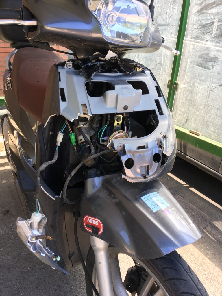
This time, they did try to steal it as it was clear they had tried to mess with the wiring. However, either because someone was exiting the building or they finally saw the 20 lb chain and U-lock on the back wheel, they weren’t able to succeed. But, again, I had a bit of a mess on my hands, and this time it seemed there was more than superficial damage.
However, strangely, the ignition still worked and none of the electrical systems appeared to have any problems.
A few days later, I took it to a mechanic to get a repair assessment. Parts and labor: 650 euros! Keep in mind, I had paid 800 for the entire thing, and to the best of my knowledge everything was fully functional. So, not wanting to shell out more than its worth for cosmetic repairs, I figured I would do it myself.
We have ignition
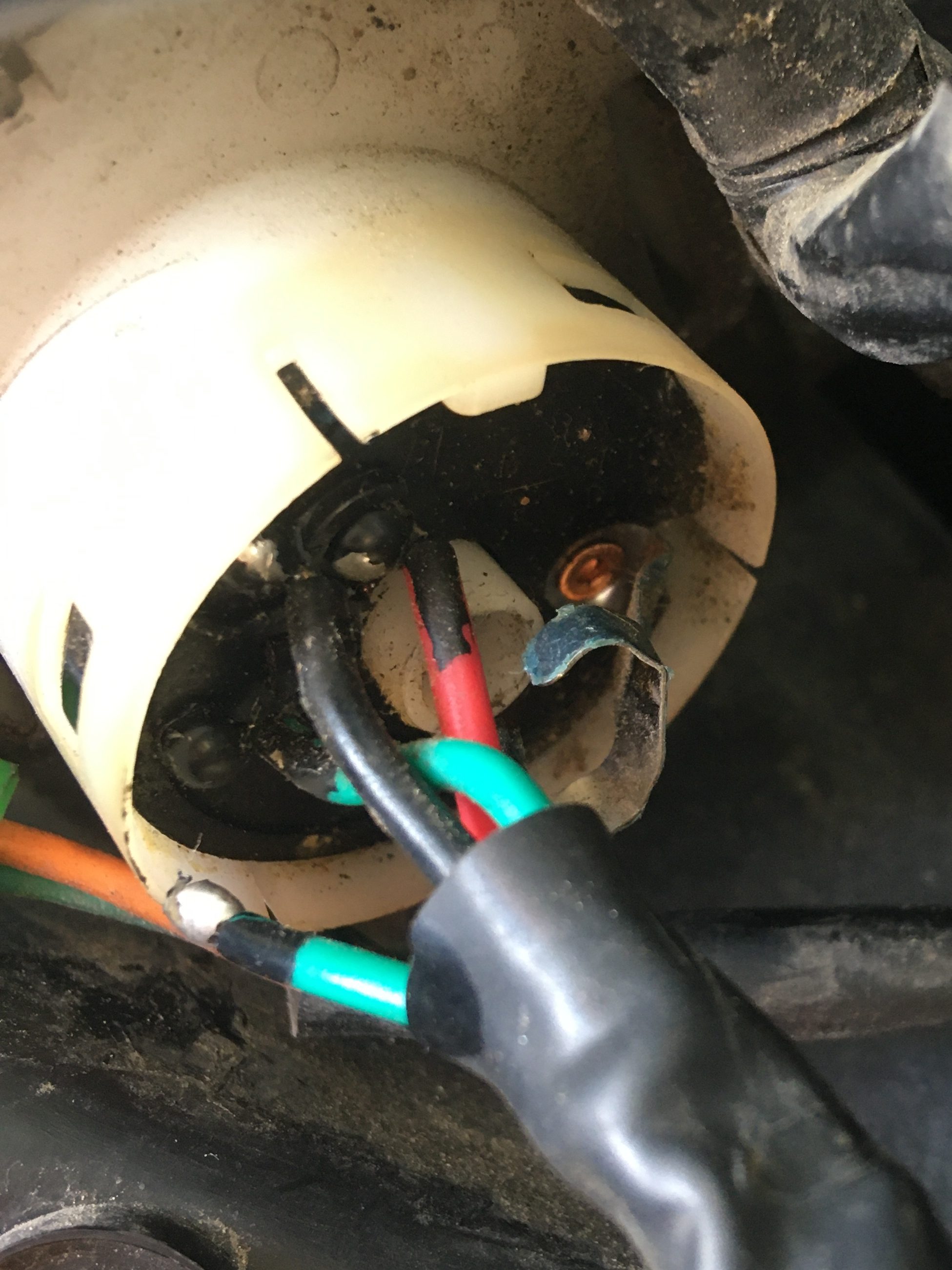
The first thing I wanted to do was to fix the wire that had been disconnected. After my May challenges where I converted a lamp to a USB plug and built an Arduino immersion circulator, I still had a soldering iron. So I removed a few screws and took out the ignition.
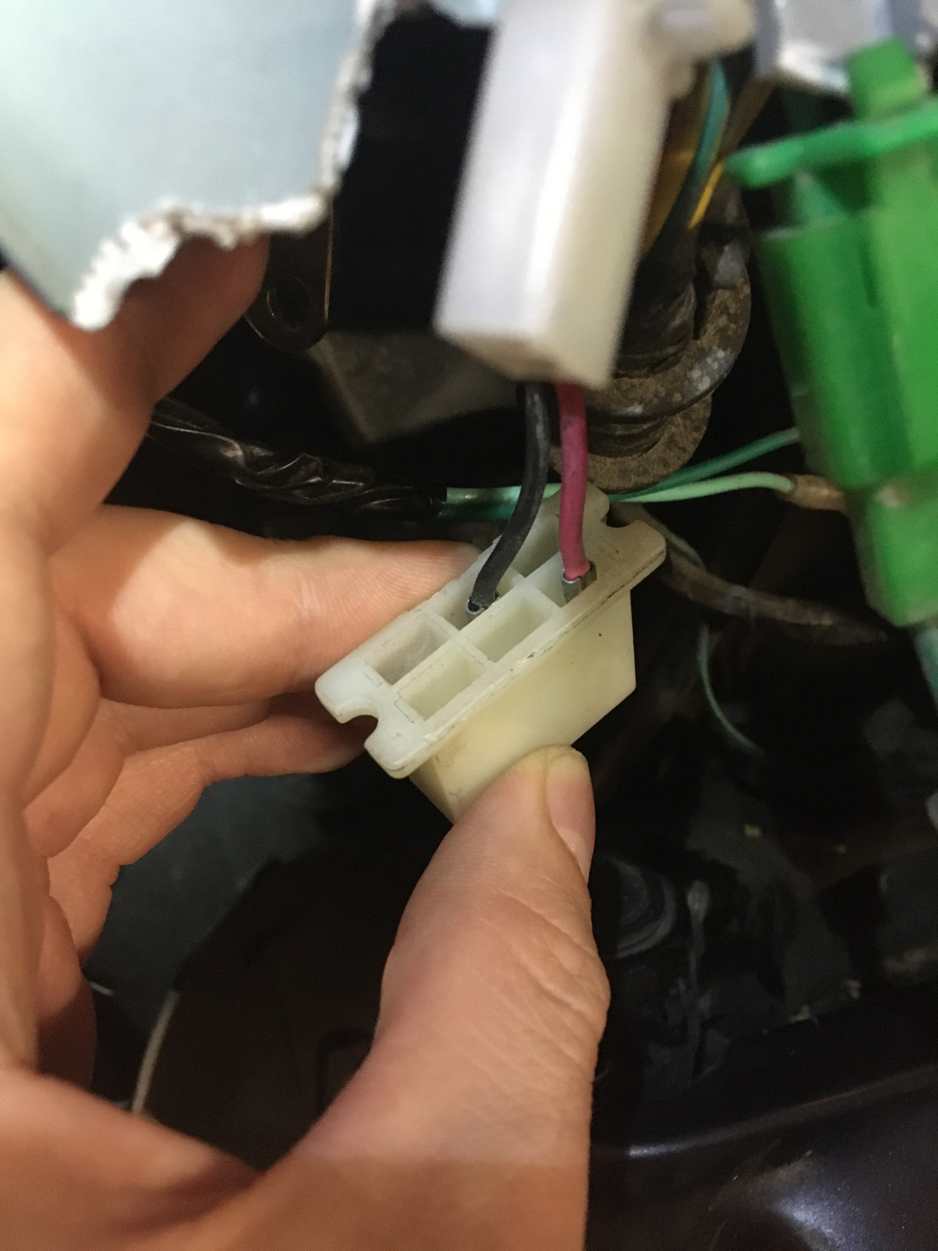
Before reconnecting the wire, though, I thought I would use my multimeter to see how it was wired inside. Setting it to measure resistance, I tried each combination of wires to see if there was little resistance (they were connected) or very large resistance (not connected) when the keys were in the ‘On’ and ‘Off’ positions.

What I found was that the two green wires were always connected to each other, and additionally connected to the black and white wire in the ‘Off’ position. The black and red wires, on the other hand, were only connected to each other and only in the ‘On’ position.
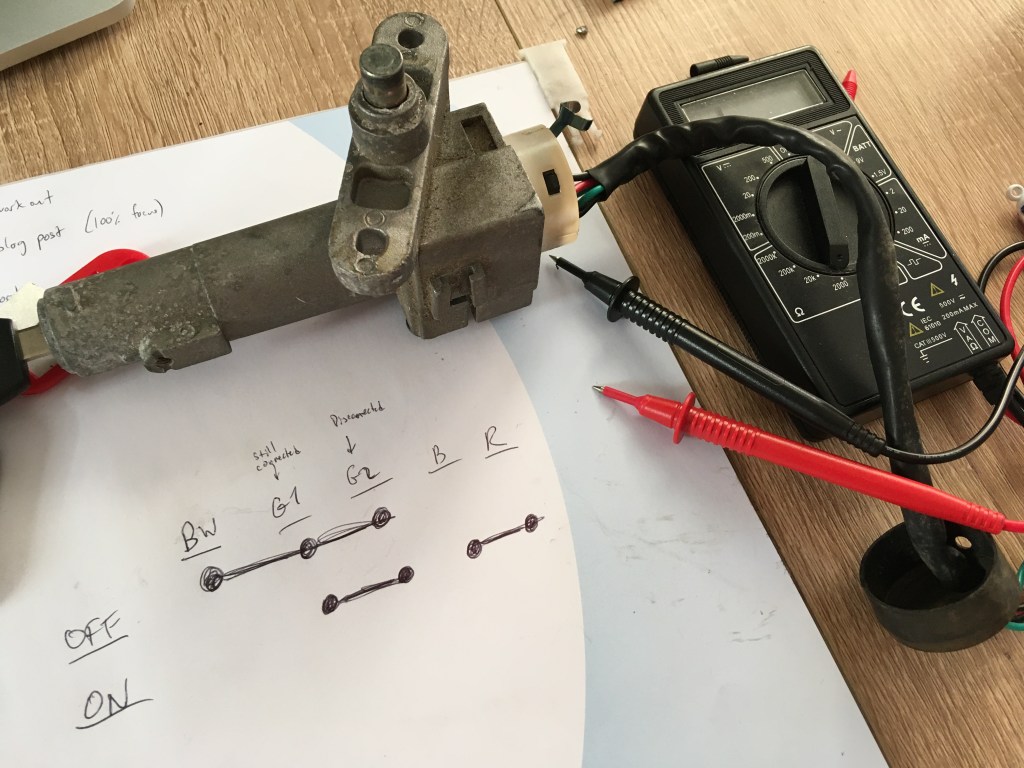
Thinking about this for a minute, that would mean two things:
- The ‘On’ signal to the ignition had to be from the red and black wires only (since the green wires were connected to each other in both positions) and
- None of the other wires seemed to be necessary, as there weren’t any electrical elements that function in the ‘Off’ position.
It seemed strange, but I decided to solder the green wire back in place and take a closer look when I reinstalled the ignition.

All you need is a paper clip
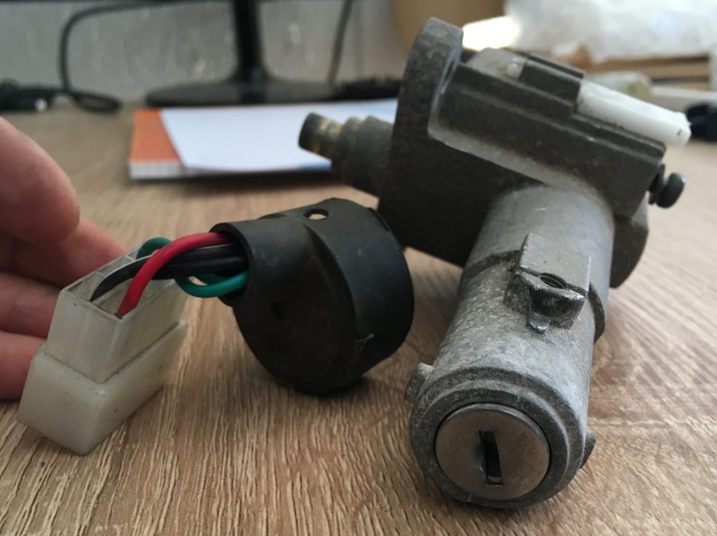
Sure enough, when I looked more closely at the ignition connector, not only were the red and black wires the important ones: they were the only wires even connected to anything on the other side! The other three wires just plugged into empty slots.
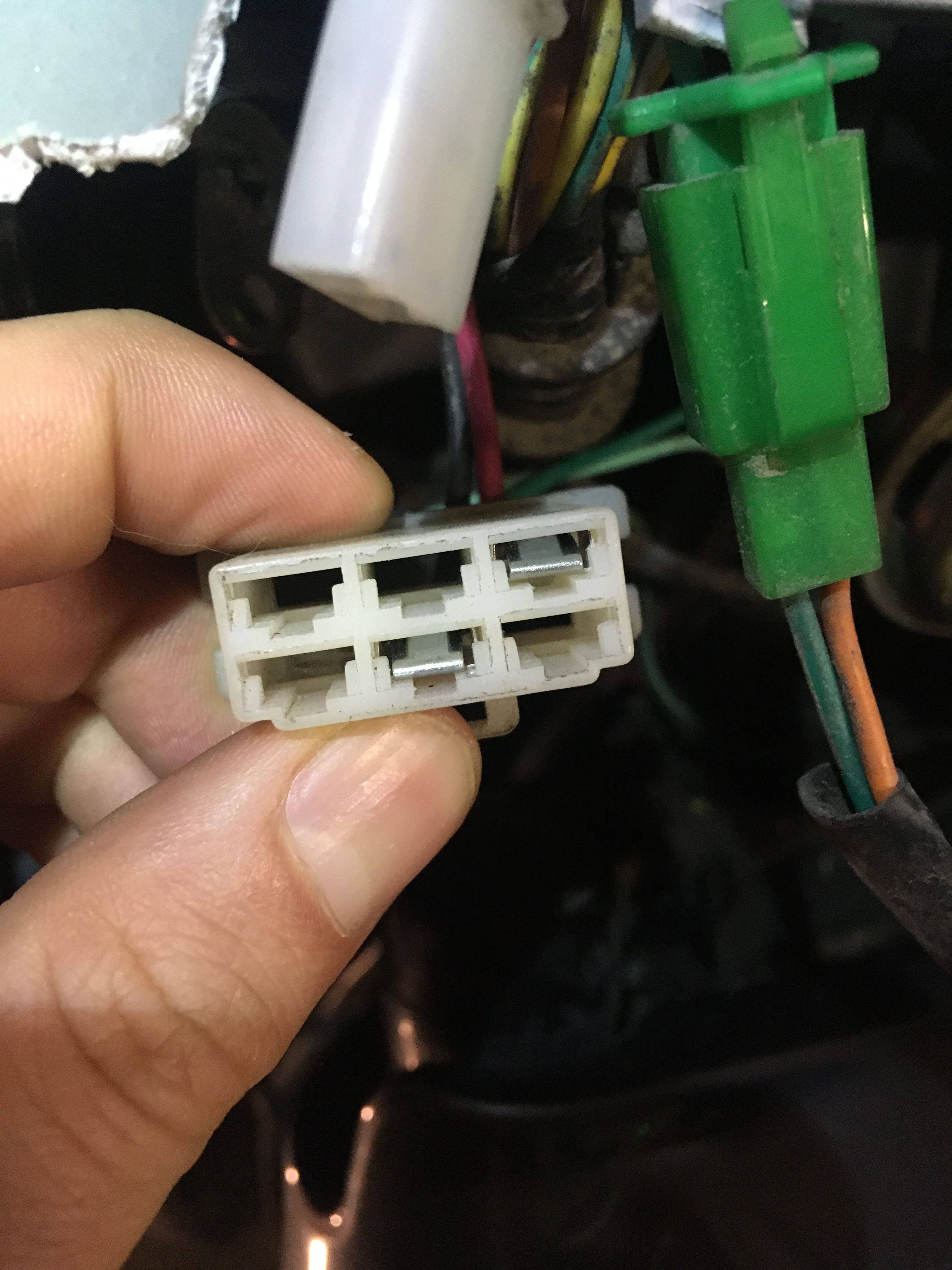
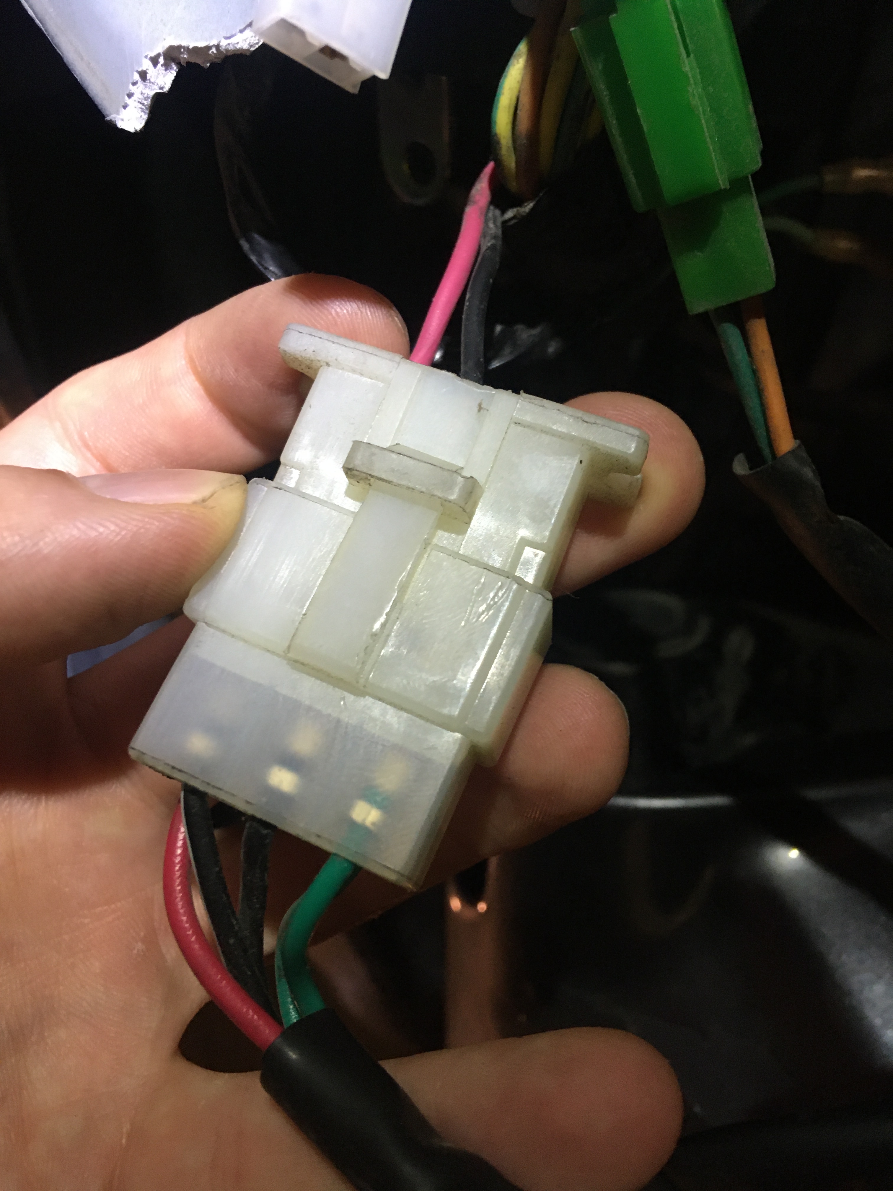
I’m not sure if this ignition is also used in other Makes/Models that have more wires to connect or if they are literally just decoys to confuse would-be thieves. But before I reinstalled the ignition, I thought I would confirm my theory: by starting the engine with no keys, just a paper clip.
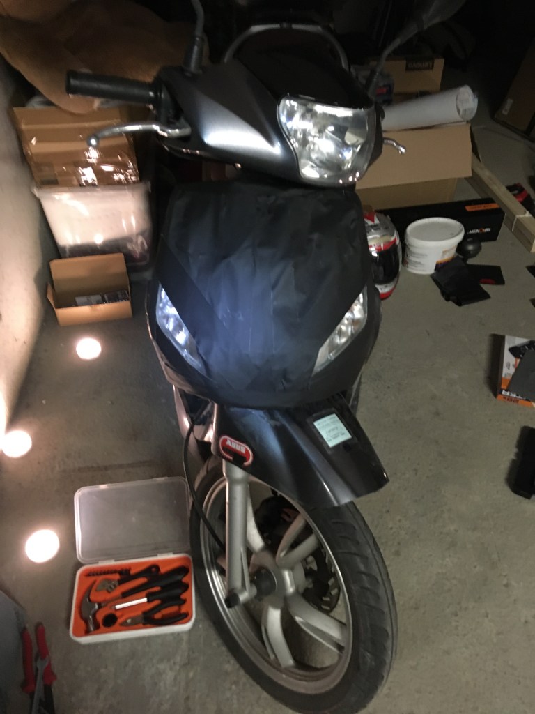
Current state of the scooter
And so knowing that all of the damage was indeed cosmetic, I redid my temporary repair of a trash bag and gaffer’s tape. Not wanting to pay more than the value of the scooter for a few pieces of plastic, I started brainstorming clever ways to fix it myself. And that is where we will pick up next time, in the last of the 2020 challenges to finish…

Pingback: How to Fix a Scooter with Legos – Chortles and Harrumphs
Pingback: How to Start a Scooter Without a Key: Bypassing the Switch